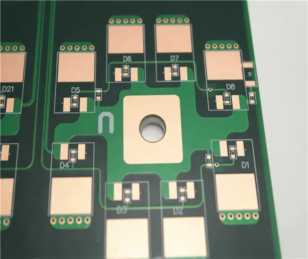
At present, there are three kinds of PCB applied with high-power LED for heat dissipation: ordinary double-sided copper coated board (FR4), aluminum alloy based sensitive copper board (MCPCB), flexible film PCB with adhesive on aluminum alloy board.
The heat dissipation effect is related to the copper layer and the thickness of the metal layer and the thermal conductivity of the insulating medium. MCPCB with 35um copper layer and 1.5mm aluminum alloy is generally used. Flexible PCB is glued to aluminum alloy plate. Of course, MCPCBS with high thermal conductivity have the best thermal performance, but the price is also rising.
Here, some data are taken from the example of MEASURING TC of NICHIA Company as calculation examples. The conditions are as follows: LED:3W white LED, model MCCW022, RJC=16℃/W. Type K thermocouple point thermometer measuring head welded to heat sink.
PCB test board: double-layer copper coated board (40×40mm), t=1.6mm, copper layer area of welding surface 1180mm2, copper layer area of back 1600mm2.
LED working status: IF-500mA, VF=3.97V
TC=71℃ was measured with type K thermocouple point thermometer. The ambient temperature TA=25℃
1. TJ is calculated
TJ=RJC x PD+TC=RJC (IF x VF)+TC
TJ=16℃/W(500mA×3.97V)
+71℃=103℃
2.RBA is calculated
RBA=(TC-TA)/PD
=(71℃-25℃)/1.99W
=23.1℃/W
3. RJA is calculated
RJA=RJC+RBA
=16℃/W+23.1℃W
=39.1℃W
If the designed TJmax is -90℃, the TJ calculated according to the above conditions cannot meet the design requirements. It is necessary to change the PCB with better heat dissipation or increase its heat dissipation area, and test and calculate again until TJ≤TJmax.
Another method is that when the UC value of the LED is too large, VF=3.65V when RJC=9℃/WIF=500mA is replaced, other conditions remain unchanged, T) can be calculated as:
TJ = 9 ℃ / W + 71 ℃ (500 ma * 3.65 V) = 87.4 ℃
There is some error in the calculation of 71℃ above, new 9℃W LED should be welded to re-test TC(the measured value is slightly smaller than 71℃). It doesn't really matter. After using 9℃/W LED, it does not need to change the PCB material and area, which meets the design requirements.


Heat sink on the back of PCB
If the calculated TJmax is much larger than the design requirement, and the structure does not allow additional area, consider sticking the PCB back to the "U" shaped aluminum profile (or aluminum plate stamping), or sticking to the heat sink. These two methods are commonly used in the design of multiple high-power LED lamps. For example, in the above calculation example, a 10℃/W heat sink is pasted on the back of the PCB with TJ=103℃, and its TJ drops to about 80℃.
It should be noted here that the above TC is measured at room temperature (generally 15~30℃). If the ambient temperature of the LED lamp TA is greater than room temperature, the actual TJ is higher than the calculated TJ measured at room temperature, so this factor should be considered in the design. If the test is carried out in the thermostat, it is best to adjust the temperature to the highest ambient temperature when in use.
In addition, whether PCB is installed horizontally or vertically, its heat dissipation conditions are different, which has a certain impact on TC measurement. The shell material, size and heat dissipation hole of the lamp also have an impact on heat dissipation. Therefore, there should be some leeway in the design.

Post time: Mar-23-2022


